MEAM.Design - MEAM 247 - P3: Concentrate - FEA
Model the Plate
1. Open SolidWorks and create a new part: File > New..., select Part
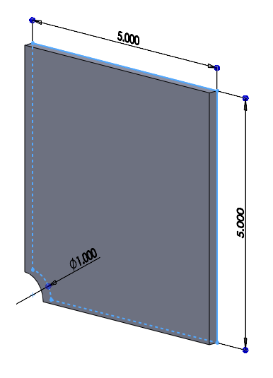
2. Sketch the profile:
- From the Sketch tab, click the 'Sketch button
- Select the Front' plane
- Using lines and arcs, create the geometry shown to the right, with the arc centered at the origin. Note that the diameter of the arc is 1 inch.
- Ensure that you sketch is fully constrained
- Exit the sketch
3. Extrude the Sketch:
- Select Extruded Boss/Base from the Features tab
- Select the sketch you just created
- Set the thickness to 0.211"
- Click the green checkmark to create the extrusion
4. Save your File:
- You may want to create a folder in which to save all your files
Set up your Analysis
1. Create the simulation files
- Click on the Simulation tab (If this does not appear, right-click on the other tabs and make sure Office Products is displayed, then click on this tab. Click on SolidWorks Office and then SolidWorks simulation to display the tab.)
- Select the drop arrow below Study, select New Study, then click the green checkmark
- Now you should see that a tab has been created at the bottom of the screen called "Study 1", and the "Study 1" feature tree should be visible below the Part feature tree in the left column.
2. Apply a Material
- Click on the Apply Material button up in the Simulation tab
- Select Custom defined, then enter the appropriate values for Elastic Modulus, Poisson's Ratio, Shear Modulus, Density, and Yield Strength for your material.
If you're having trouble:
- right click and select "New Library", name it whatever you want
- right click on the library you just made and select "New category", name it what you will
- right click on the category and select "new material", make sure that you edit all the proper values (Elastic Modulus, Poisson's Ratio, Shear Modulus, Density, and Yield Strength) BEFORE hitting save.
- Hit save, you will get an error
- Navigate back to the material you just made and hit "Apply"
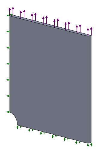
3. Apply Constraints (Fixtures)
- As we are only modeling a quarter of the plate, we need to apply a Symmetric constraint to the two cut edges. Do this by selecting the drop arrow below Fixtures in the Simulation toolbar, then selecting Advanced Fixtures
- Click on Symmetry
- Select the two symmetric faces
- Click the green checkmark
- We also need to constrain out-of-plane motion of the plate by adding a Roller constraint to the back of the plate. Do this by selecting the drop arrow below Fixtures in the Simulation toolbar, then selecting Roller
- Select the rear face of the plate
- Click the green checkmark
4. Apply External Loads
- To apply the load, select the drop arrow below External Loads in the Simulation toolbar, then select Force
- Select the top face of the plate
- Enter the desired load
- You may need to select Reverse Direction to ensure that the force will be tensile
- Click the green checkmark
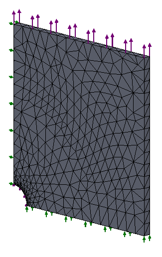
5. Define the mesh
- Right click on Mesh in the Study-1 tree, and select Create Mesh
- To see the default mesh, select the green checkmark
- Notice that you can tighten the mesh using the slider under Create Mesh
- You can add mesh refinement to specific geometry by right-clicking on Mesh and selecting Apply Mesh Control
- Once you set up mesh control, you need to select Create Mesh again
Run the simulation
- Click the Run button in the Simulation toolbar
- Wait
- To change what is viewed or how it is displayed, right click on the specific result and go through the various options