MEAM.Design - S62 - Using BoardMaster
<< Generating tool paths from Gerber Files | S62 | >>
Initial Setup:
Before you can start, you have to cover both copper surfaces with plastic, so that the solder plating (in a later step) doesn't get all over the surface.
First place your blank PCB sheet on top of a sheet of the plastic sticker material and mark around the edges so that you can cut it.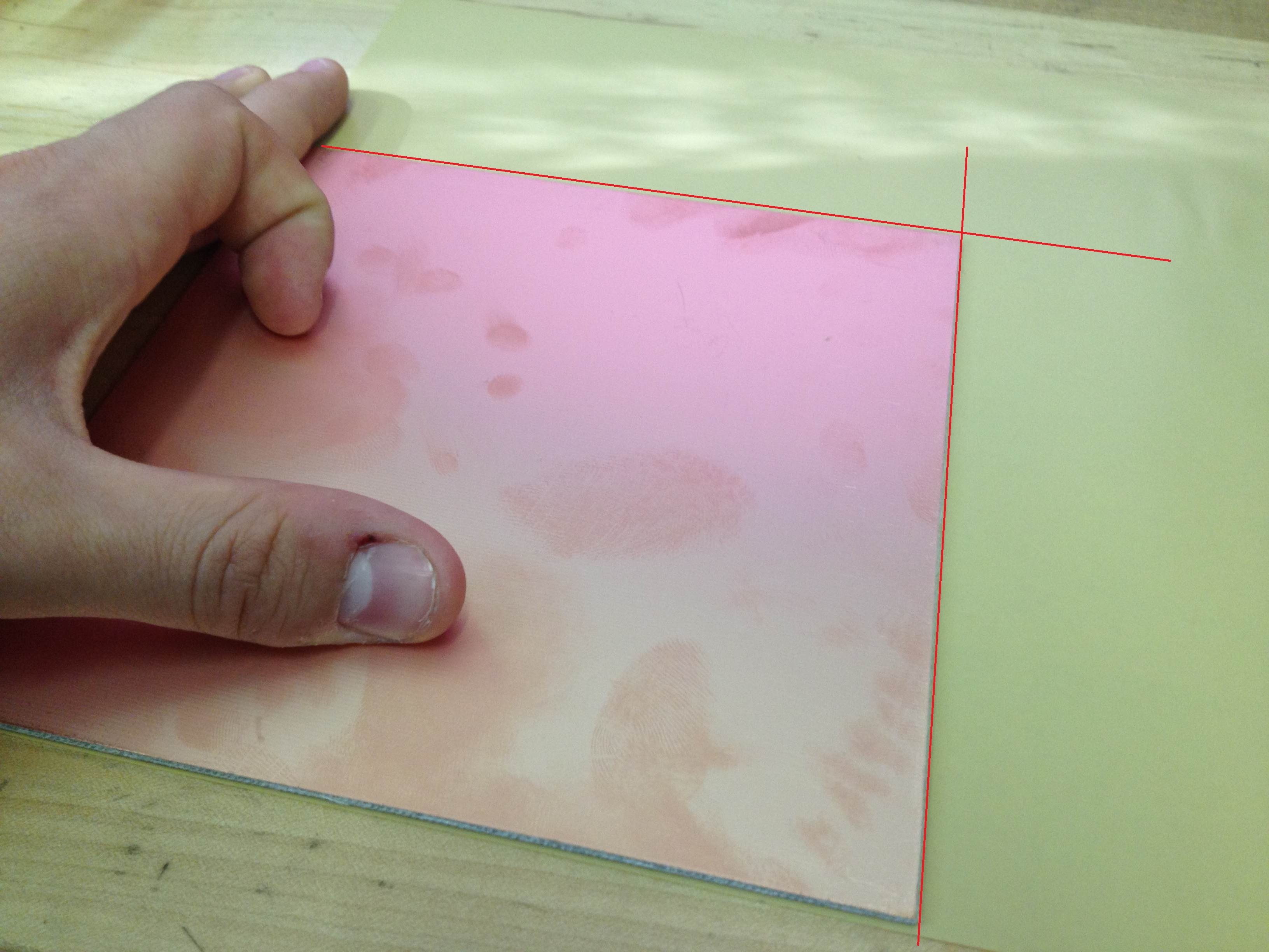
Now carefully cut where you marked, so you get two stickers that can perfectly cover the front and back of the PCB.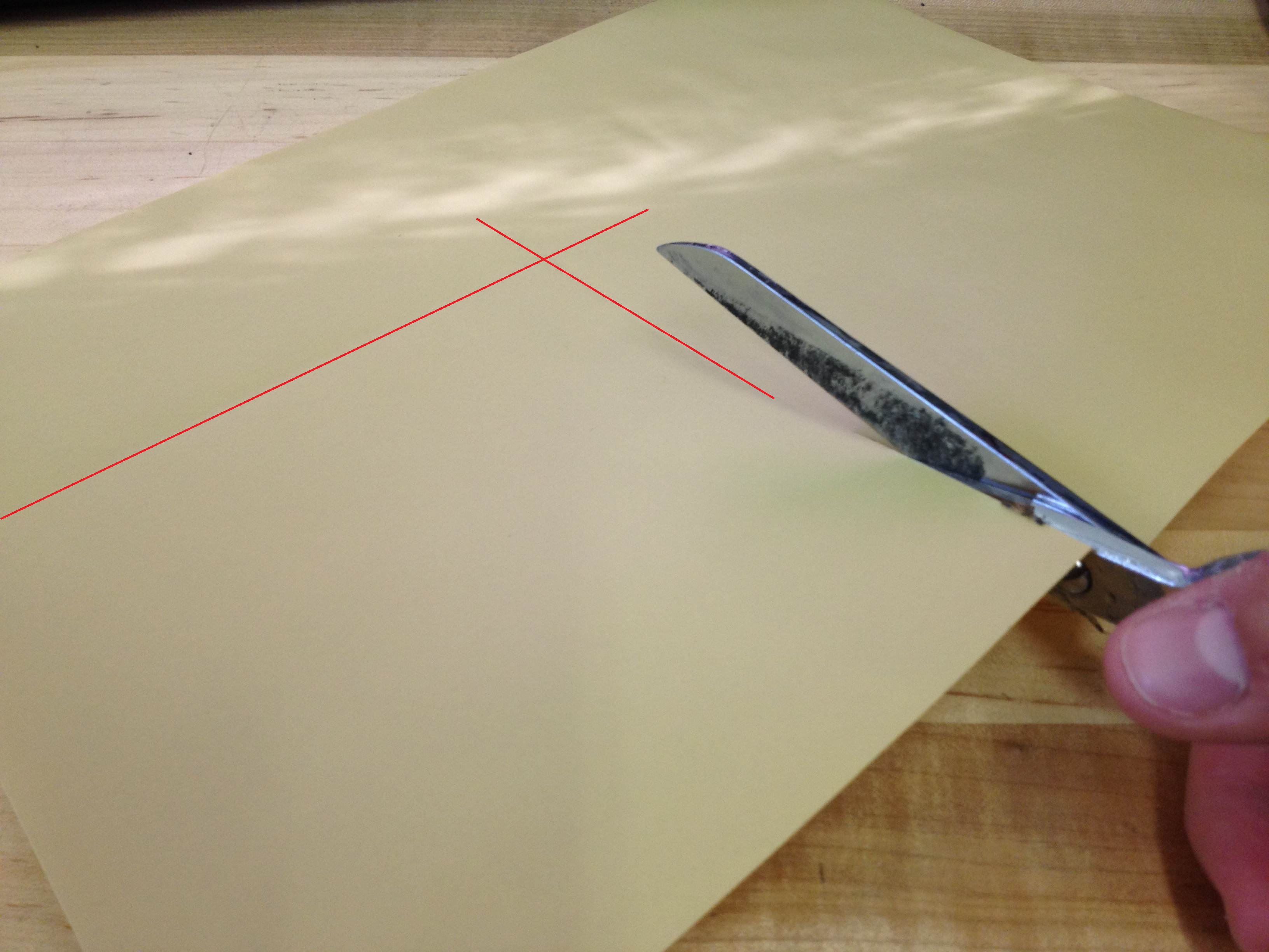
Peel the backing off the sticker. Discard the backing, and keep the sticker.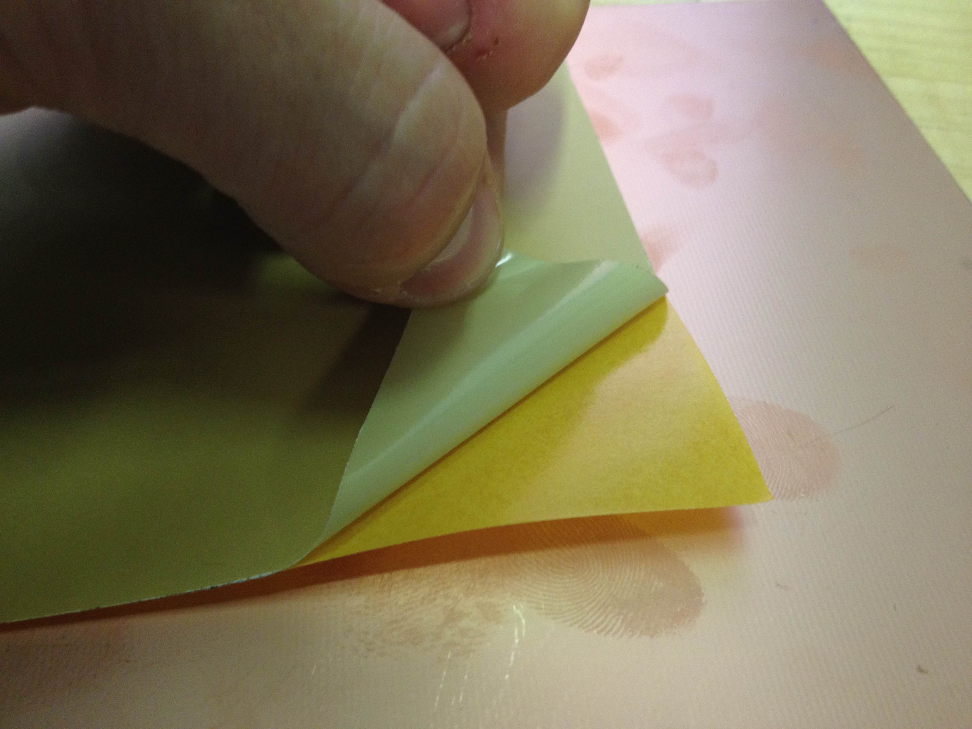
Stick one edge of the sticker on the copper, ensuring careful alignment.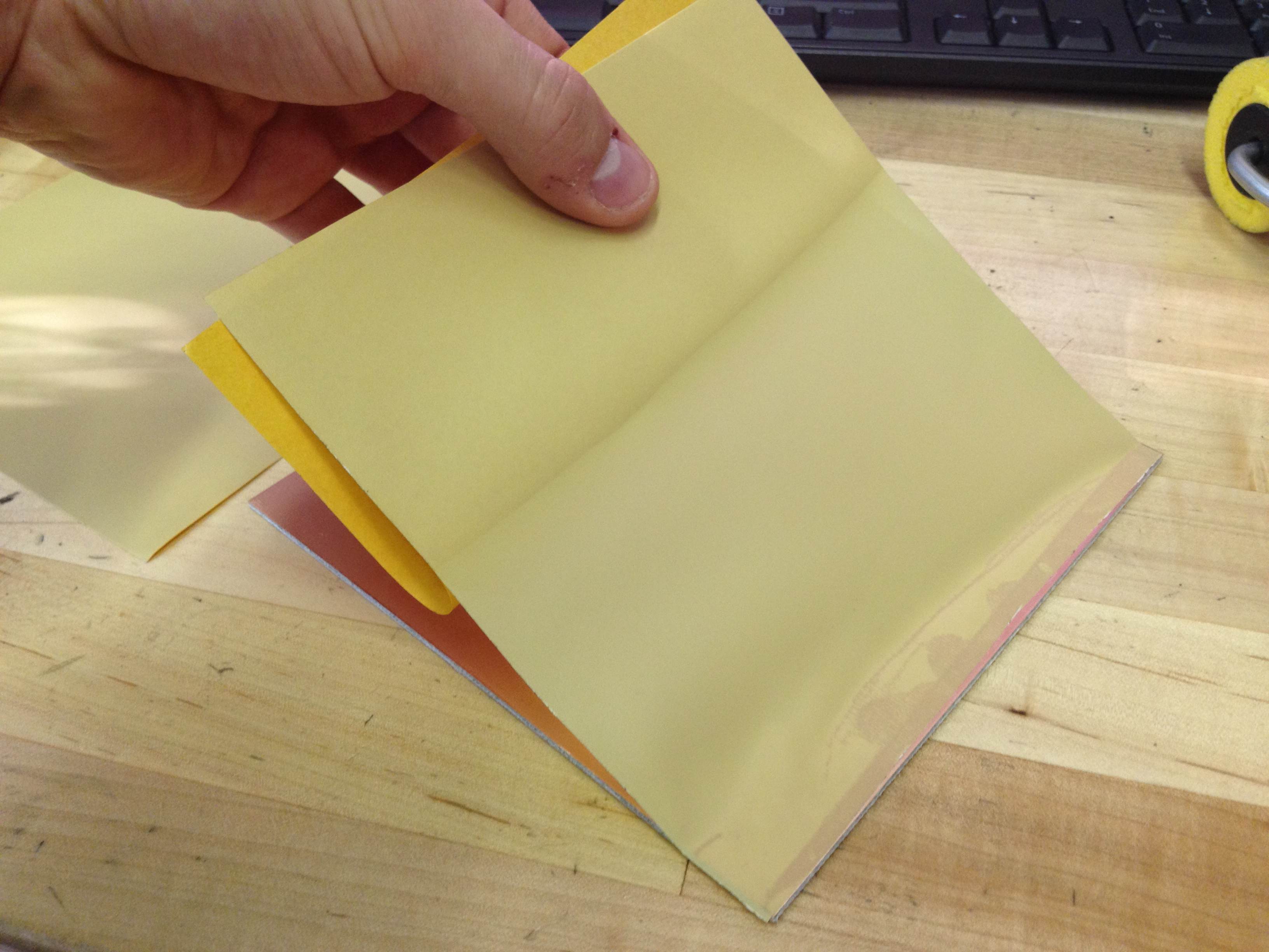
Use the yellow roller to carefully press the sticker onto the blank PCB. Do this slowly from one edge to the other, and avoid bubbles as much as possible.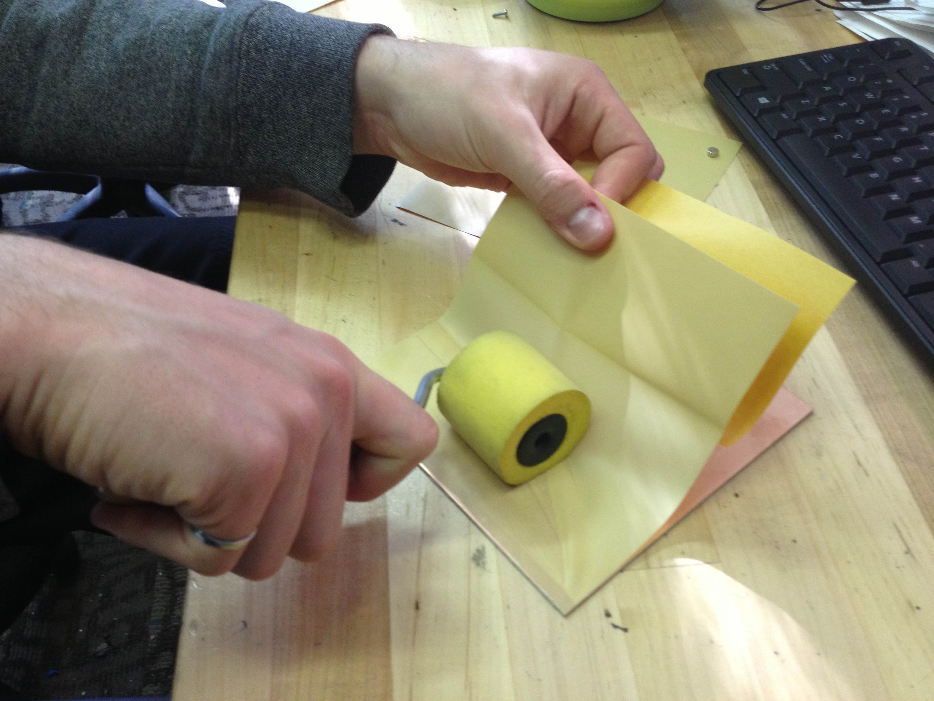
If you trap air under the sticker it will form bubbles as shown below. This could prevent good plating, so you'll have to peel it back and re-apply it to correct the bubbles.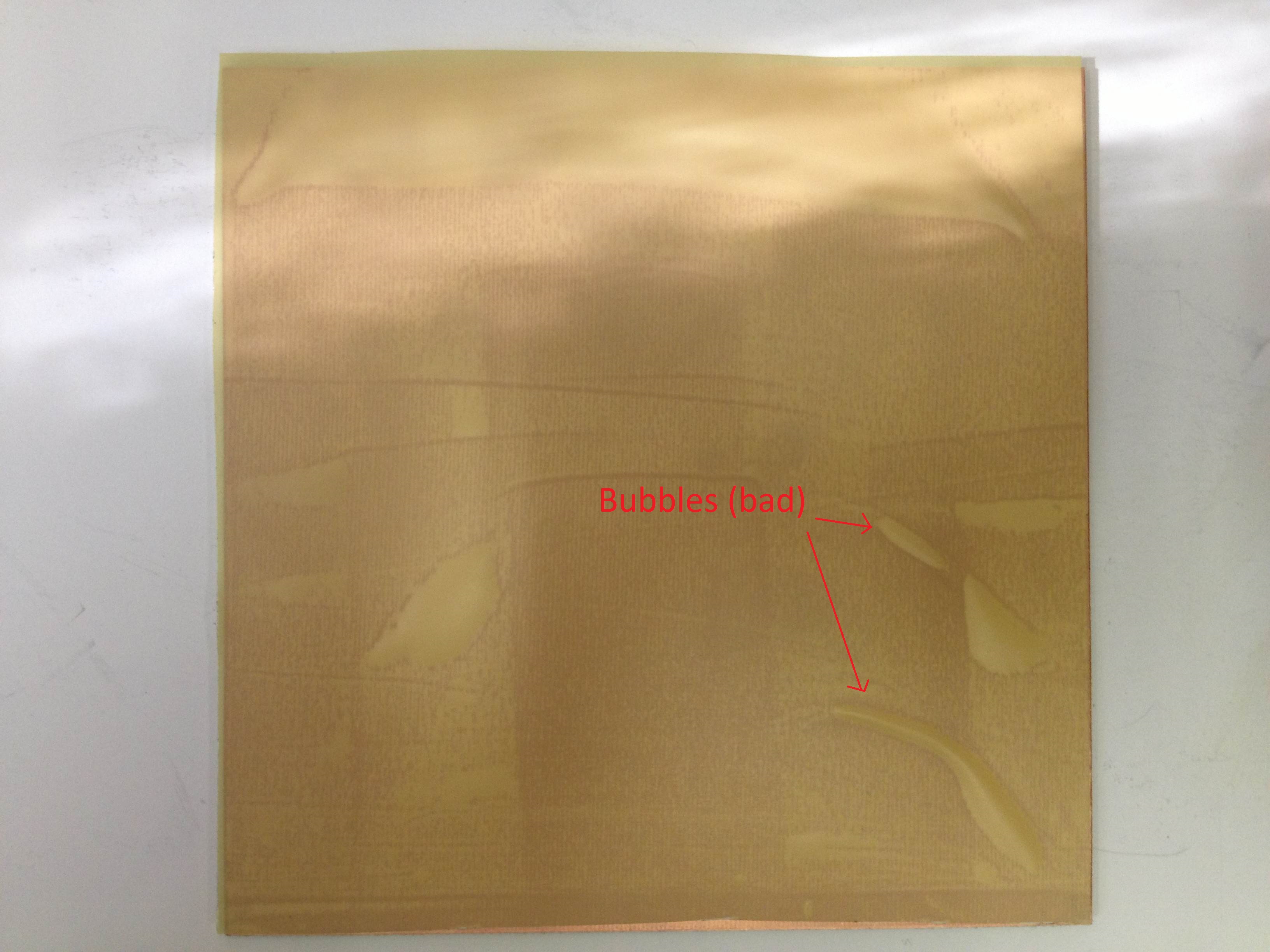
Below is an image of what a good sticker, with very small bubbles (or none at all) looks like. This is acceptable for through-hole plating, which is explained in the next step.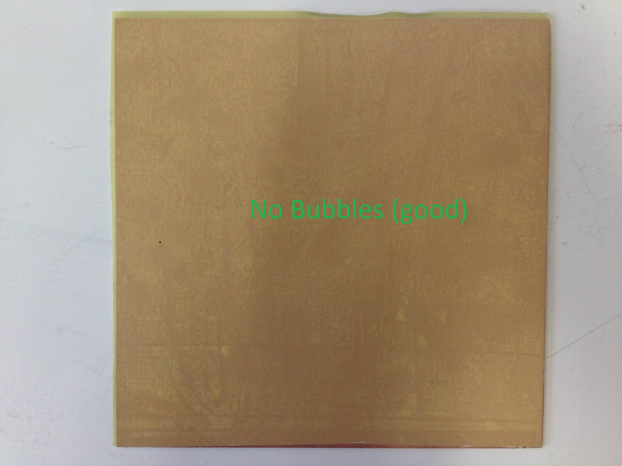
Production:
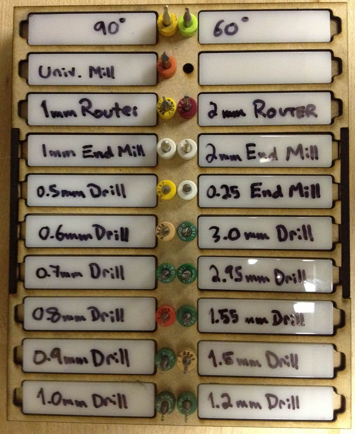
The tools for the S62 are stored in a tool holder block, pictured below. Basic guidelines for proper use of tools are as follows:
- Always remove tools from the tool positions of the S62 after a job, and return them to the tool holder.
- Always return tools to the correct spots on the tool holder, or if you must change where the tool goes, ensure you also change text on the white plastic label next to the tool.
- When a tool gets broken, or too worn for continued use, discard it in the trash and replace it with a brand new one.
- When replacing a old tool with a new one, remove it from the clear plastic tool boxes and keep it in the tool holder, DO NOT return it to the clear plastic tool boxes.
Through Hole Plating Process
# Read Bottom
Assuming the through hole plating is complete and the board has cooled, you may begin milling the bottom features of your circuit board. Ensure that the white fiber board is installed in the vacuum table. Place your PCB on the vacuum table with the bottom side facing up, ensuring it's orientation is correct. Turn on the vacuum system.
Select the 'Read Bottom' step from the task pulldown menu. Click 'All +', then click 'Start'.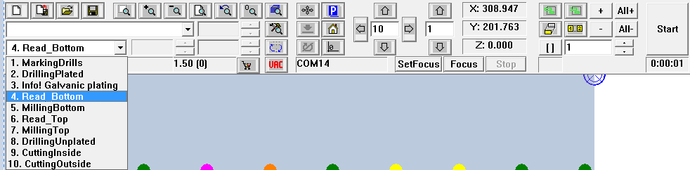
Board Master may give you a popup dialog like the one below. If you encounter this, click 'YES'.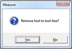
The S62 will move the milling head and release whatever tool it is holding. Then it will move to approximately where it thinks the first fiducial is. It will run an algorithm to try and align the center of the fiducial with the center of the camera's optical axis.
The alignment likely won't be perfect. You will see a window like the one shown below in Board Master. 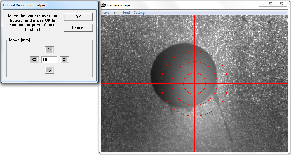
Use the arrow keys and number form field to reposition the camera until the circle is aligned with the fiducial in the window that is displayed in the Board Master software. Take care to do this as precisely as possible.
Once you are satisfied with the position, click 'OK'. The S62 will move to the next fiducial, and you will have to repeat the process that you just completed on the first fiducial. Continue this process until the S62 has had a chance to read all 4 fiducials.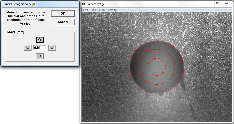
Occasionally, the camera's exposure is very bad, making it difficult, or impossible for you to know if you have achieved good alignment of the camera's optical axis and the center of the fiducial hole.
When this happens, you can adjust the exposure. In the 'Camera Image' window, click 'Setting'. A window will appear, giving you many options. This menu cannot be used to focus the camera, but you can slide the brightness and contrast bars, to change the apparent exposure of the camera.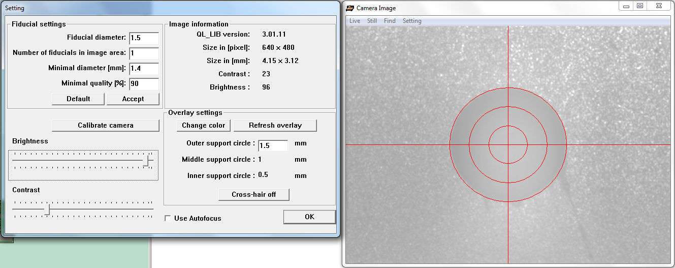
Once you are satisfied with the adjustments, it should look much more obvious where the hole is (compare the image below with the one above). Click 'OK' to proceed with the new exposure settings you have chosen.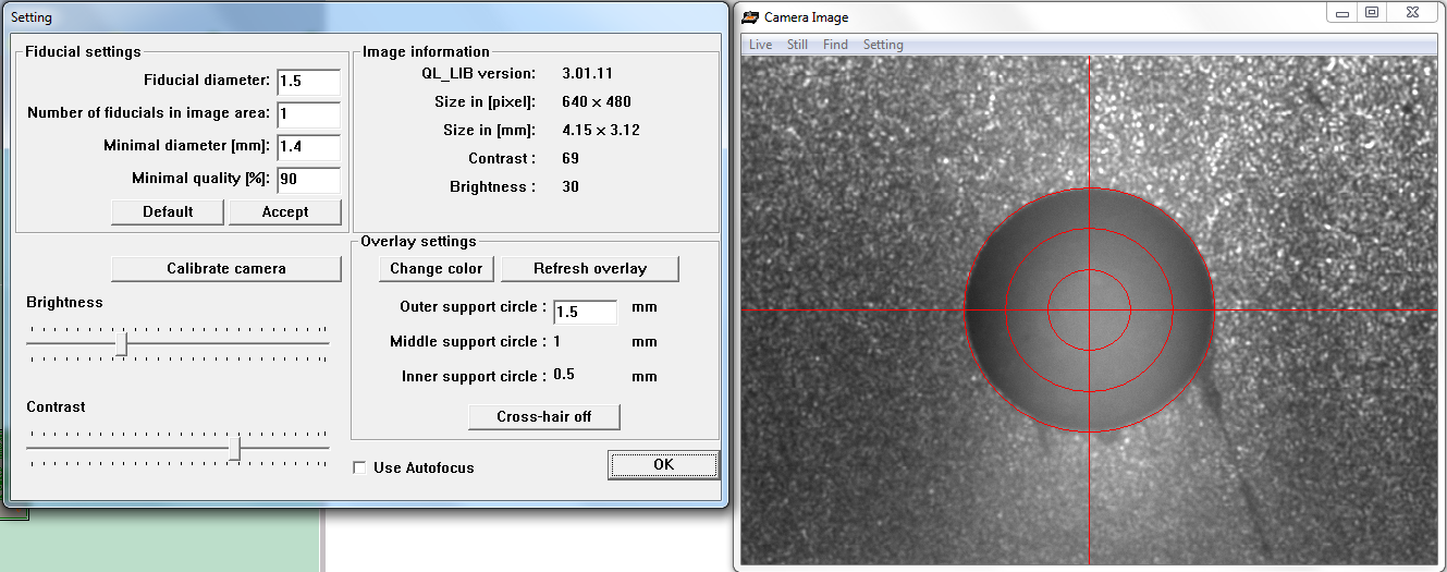
Sometimes, the Board Master software detects an error in the fiducial reading process. When this happens, you may see an error dialog box, such as the one shown below.
This is a good indication that the S62 doesn't have a correct position reading (or ANY position reading) for your board. You must repeat the 'Read Bottom' procedure, so that the S62 has a another opportunity to run through the fiducial recognition process and store the board's coordinates.
Click 'Cancel' and start at the beginning of the 'Read Bottom' procedure. Do not proceed until you have successfully completed the 'Read Bottom' procedure.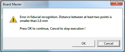
If the error message does not appear, you can assume that the S62 has successfully read the fiducial positions. You can continue to the next steps.
# Mill Bottom
Now you are ready to mill the board's bottom features. The top features will follow, in a later step. Select 'Milling Bottom' from the task pull down menu. Click 'All +', then click 'Start'.
A dialog box will appear, as shown below. This indicates that the S62 wants you to add the tools into the tool holders that it needs for the task it is about to do. Press 'OK'.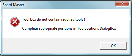
The S62 will want to move the spindle into the 'PAUSE' position to allow you to change the tools in the tool holders. A a dialog like the one below will appear. Click 'YES'.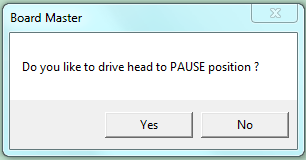
The 'Tool Position' Menu will appear. The left list has several pulldown menus. You use these to tell the S62 which tools you have put into it's holders. They are numbered 1 - 10 from left to right.
Do not use tool holder 1. In the past, it has become jammed several times. Leave it empty.
The right list tells you which tools the S62 needs in order to complete the task that you are presently working on. You must ensure that the required tools are installed in the tool holders, and then tell the S62 which positions they are in, using the pulldown menus on the left.
The image below is given only as an example of the 'Tool Position' menu. For the Mill Bottom step, you will likely want a Universal Cutter 0.2mm and an End Mill 1.0mm.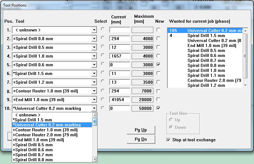
The Universal Cutter 0.2mm was already in position 10, but it was selected as a marking tool, so the S62 considered it unavailable for the milling task. Change it to '0.2mm Universal Cutter' to tell the S62 that you intend to use it for this task (the 'Milling Bottom' task).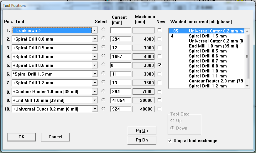
Press the 'OK' button when you have finished making changes to the tools and tool positions.
The S62 will pick up the first tool that it needs (probably the Universal Cutter 0.2mm), and position itself to begin the first step of the MarkingDrills task.
The S62 doesn't have a method for determining if the tool tip has the correct z-position by itself. A dialog will appear like the one below, asking you if you want to check and adjust the z-poisition before you start.
It is a good idea to always verify the z-position after a tool has been picked up, in case the chuck is gripping the shaft at a different height compared to the last time it was used. Also, it is common that the z-position is adjusted between tasks, so now is a good time to ensure it is correct for this step.
When this dialog appears, click 'YES'.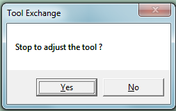
In Board Master, use the 'Position' Tool to move the spindle above an area of the board you don't mind marking (an area outside the rubout area you defined in CircuitCAM)
Start the spindle (make it turn).
Lower the spindle so the tool bites into the board, by pressing the raise/lower spindle button.
Use the 'Left' or 'Right' arrow to make the spindle displace 4mm to the left or to the right.
Now raise the spindle by pressing the 'raise/lower' spindle button a second time.
Park the spindle by pressing the 'Park' button.
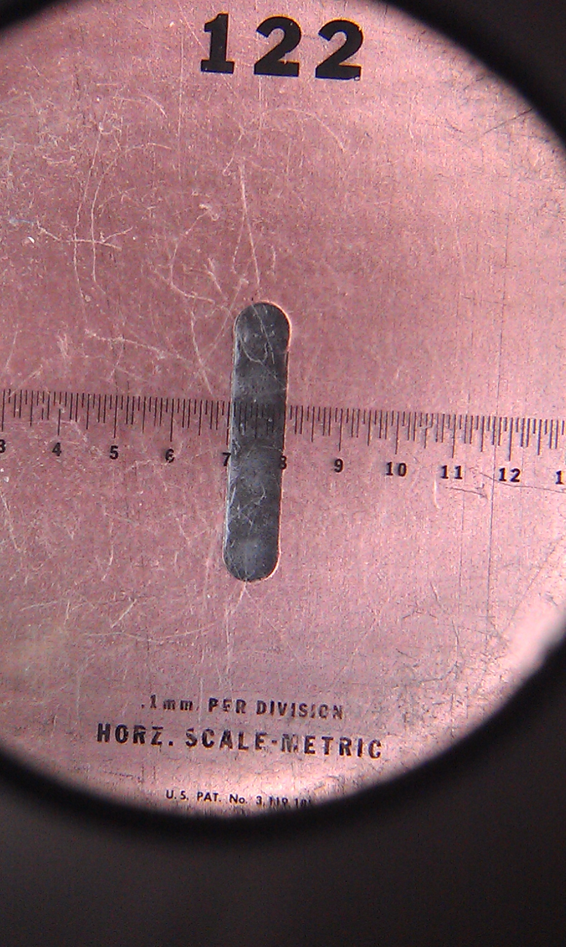
Open the cover and use the magnifying loupe to check the size of the mark that was made by the tool on the surface. 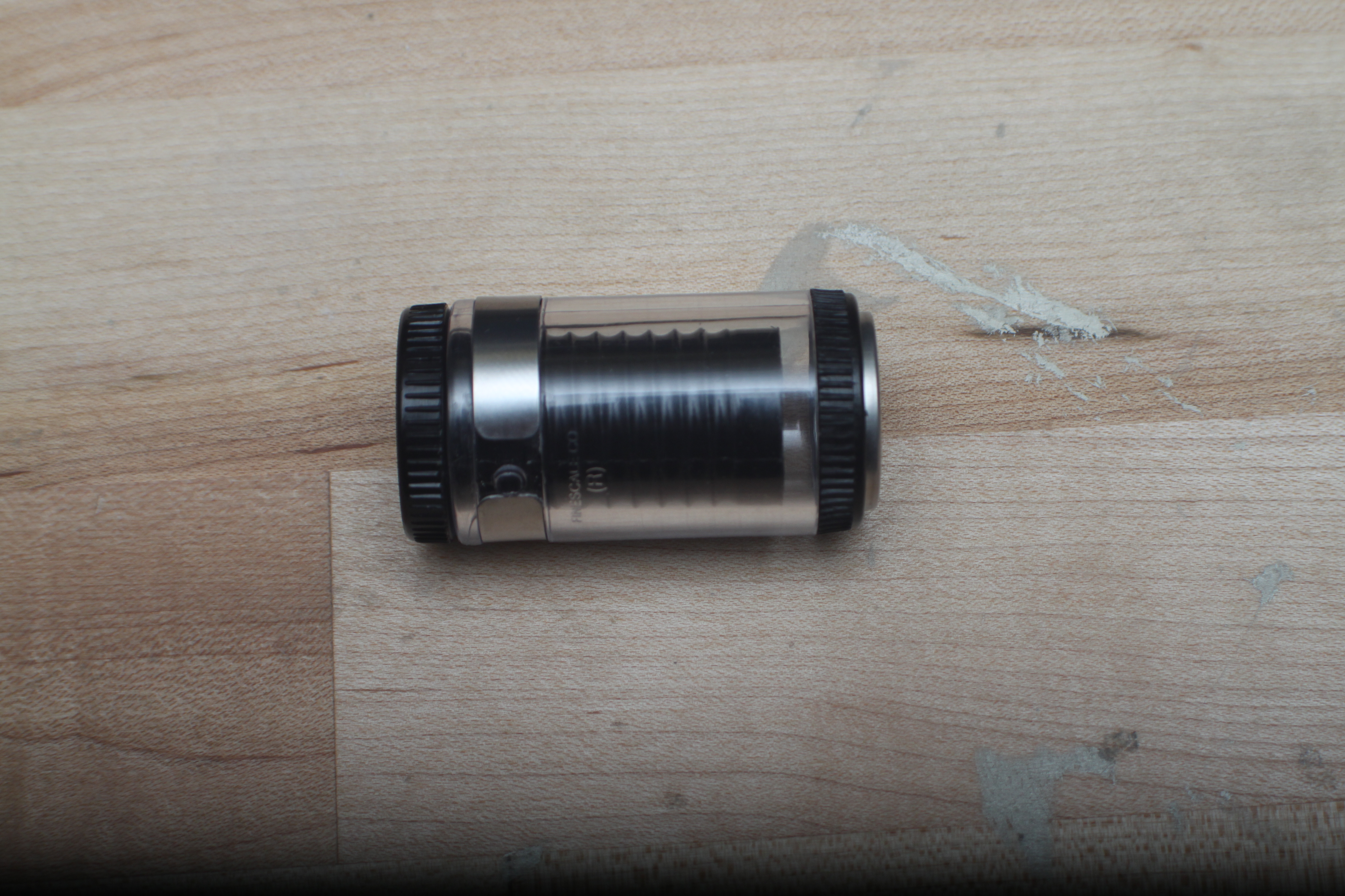
Below are images of what you will see in the loupe if the tool was too high above the board's surface (left) compared to what you will see if the tool is adjusted correctly (right).
Notice the small chips of copper that remain in the left image. This is a sign that the tool was only barely touching the surface of the copper, so it failed to completely remove all the material in it's path. 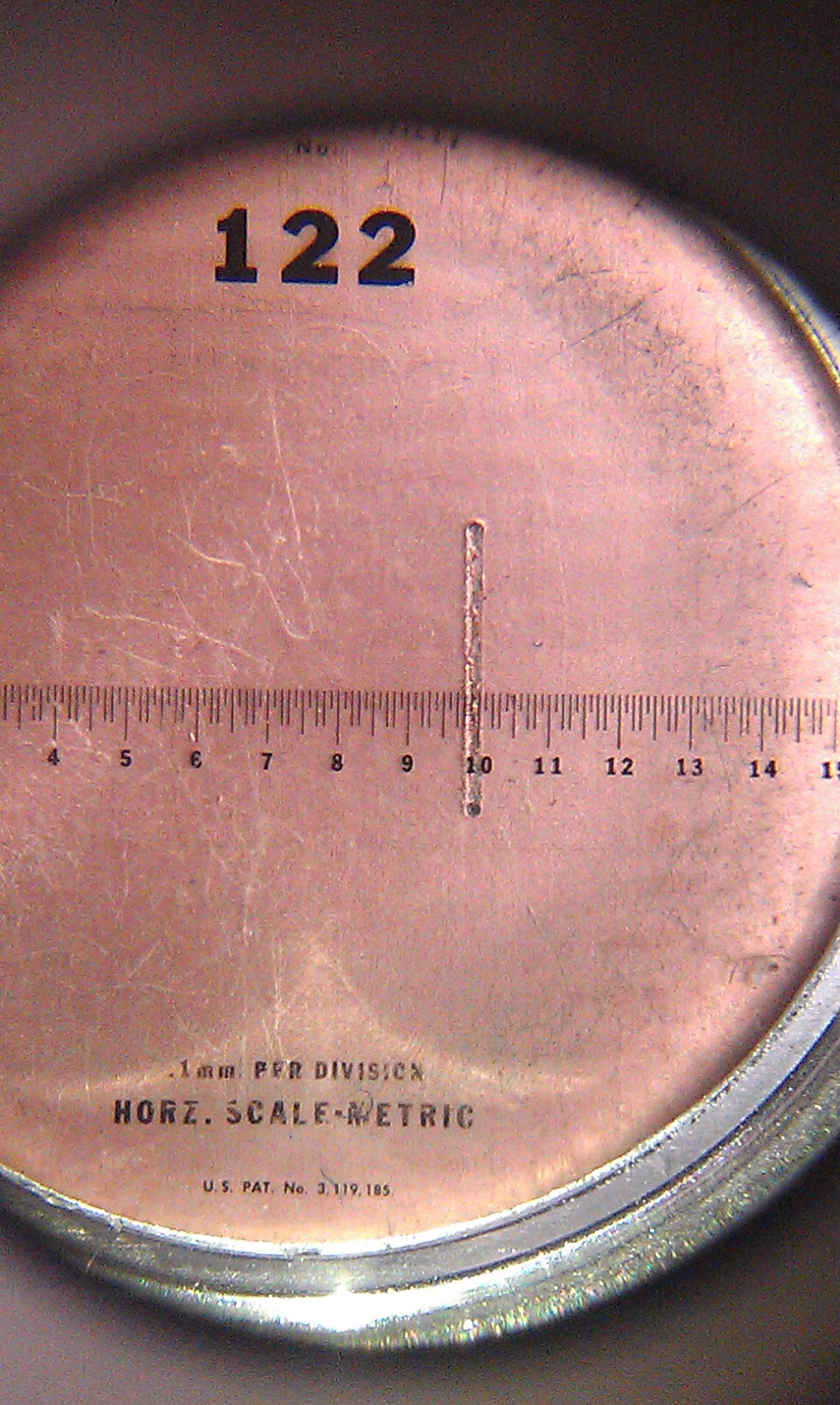
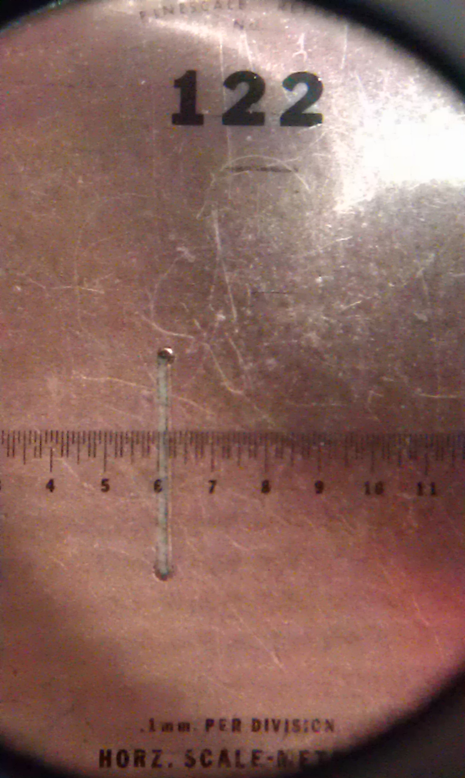
It is critical to get the thickness of the cut just right. Use utmost care to measure it precisely using the scale that is visible when you look through the loupe.
Below is an image of the surface of the board after the test cut, seen without the aid of the loupe. 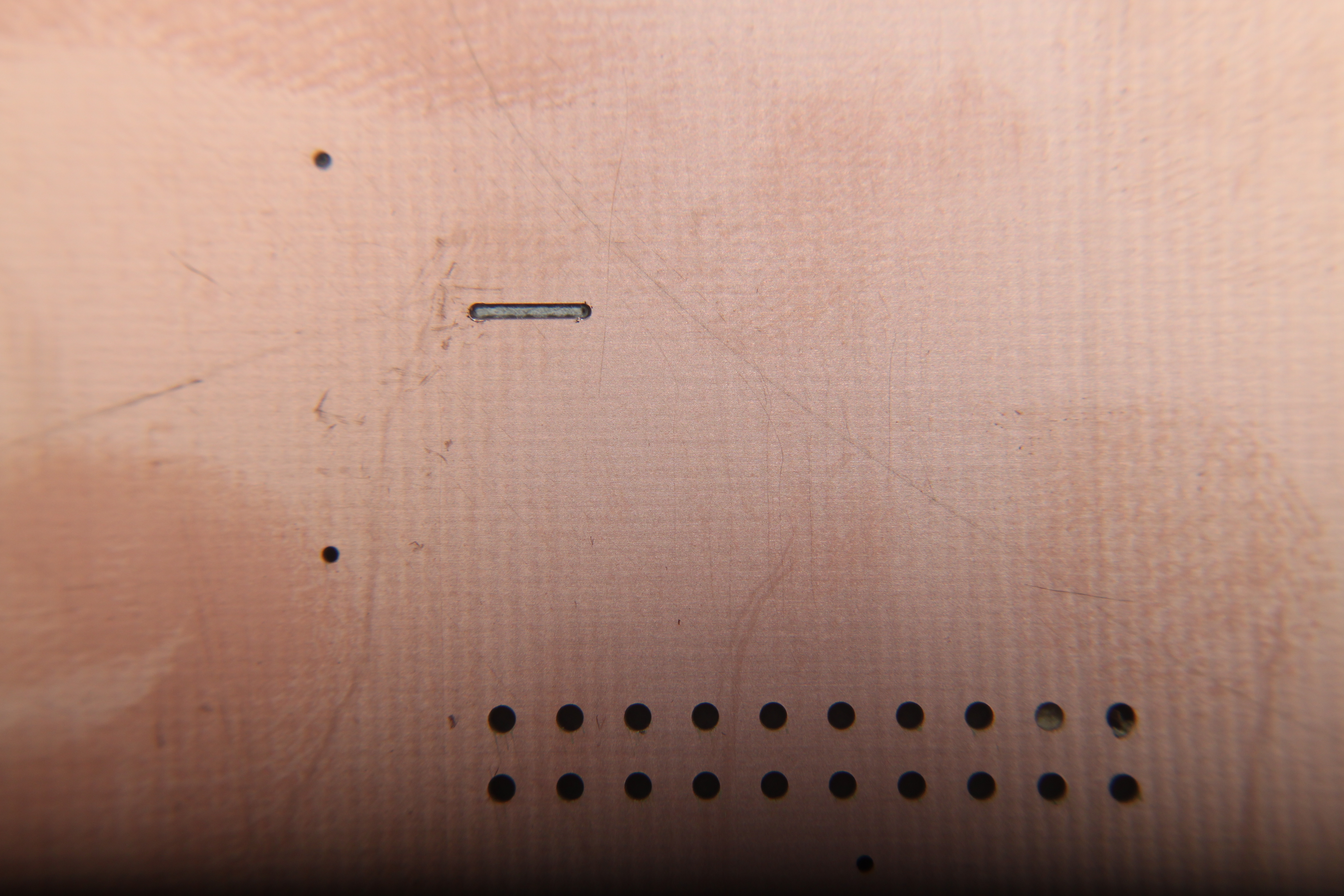
If the tool did not touch the surface, or if the tool made a very deep mark, the z-axis must be adjusted down/up by rotating the collar of the spindle clockwise or counter-clockwise. The spindle collar is the black knurled ring, shown below. 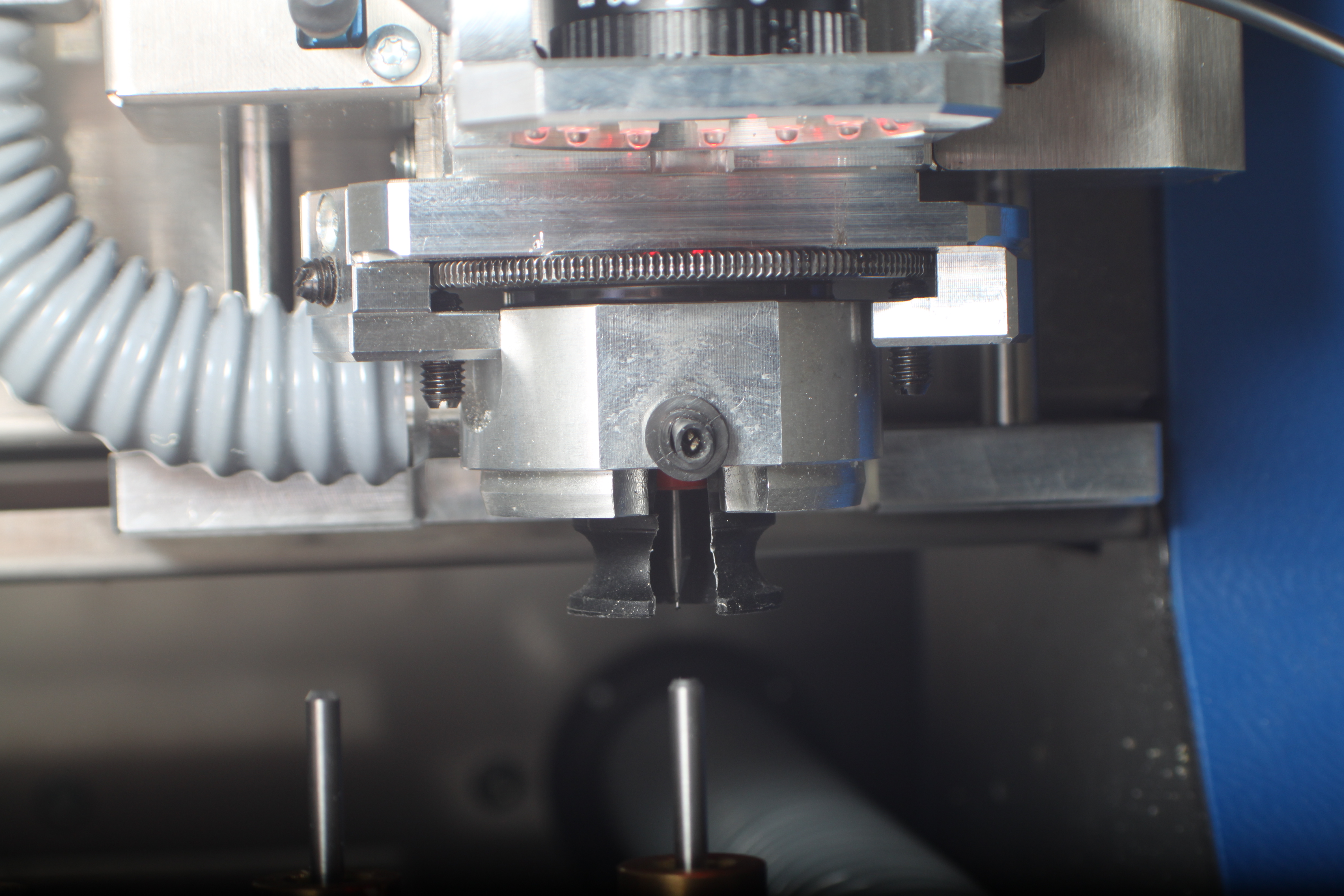
Adjust the spindle and make new markings on the surface of the board until the z-axis height is correct.
Once you have the z-axis set, move the spindle back to the 'Park' position.
Press 'Start' and watch carefully as the S62 begins to mill the small features.
Once it has finished, it will automatically grab the larger tool and position the tool to begin milling the large features.
It will pause and ask you if you want to adjust the tool:
Click 'YES', and repeat the tool adjustment process that you used to get the correct z-height for the small cutting tool.
Below are images of what you will see in the loupe if the tool was too high above the board's surface (left) compared to what you will see if the tool is adjusted correctly (right). 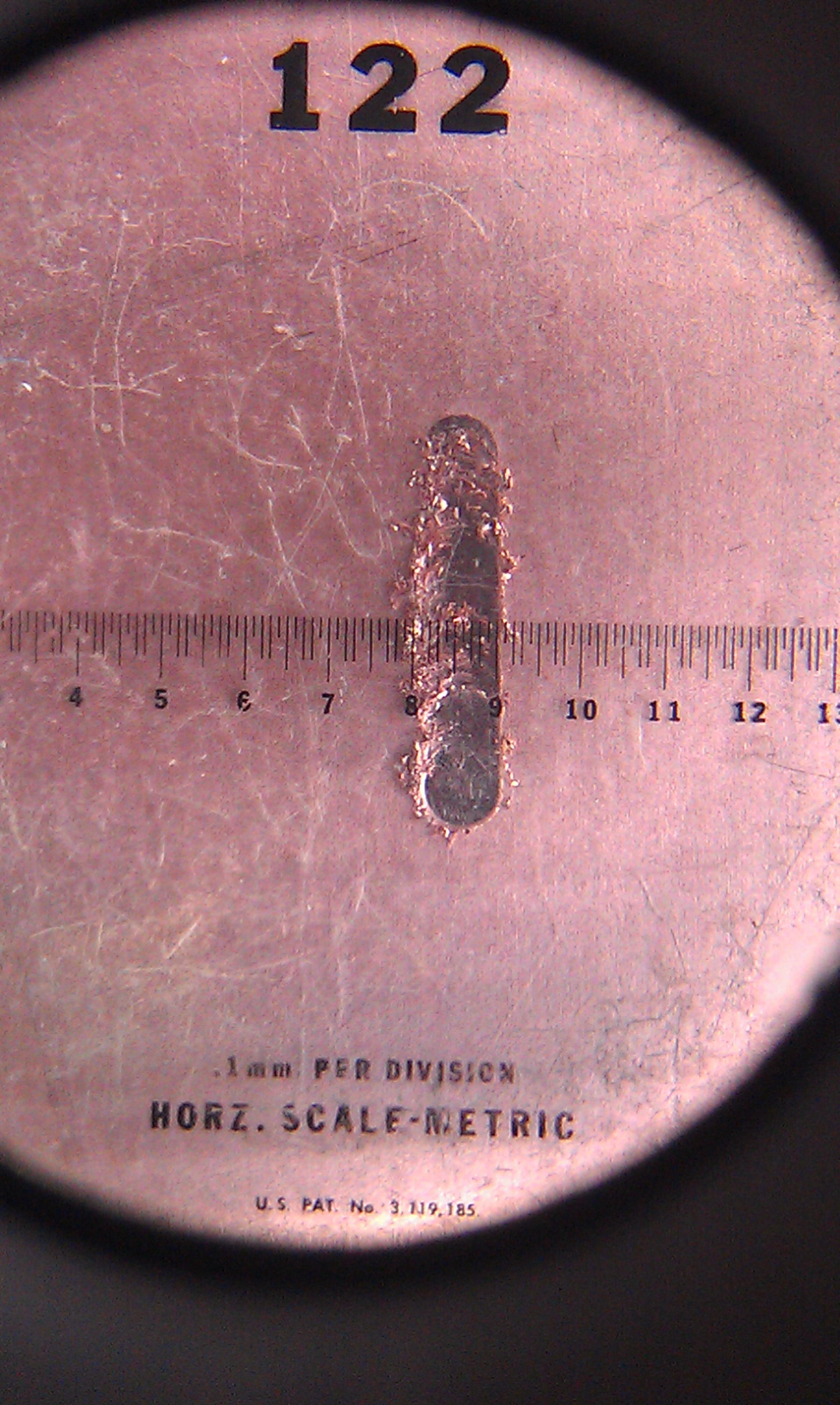
Once you are satisfied with the z-position, click 'Start' and watch again as the S62 mills the large features.
When it has completed this step, move the spindle to the 'Park' position.
Below are some images of what the end result might look like, as an example: 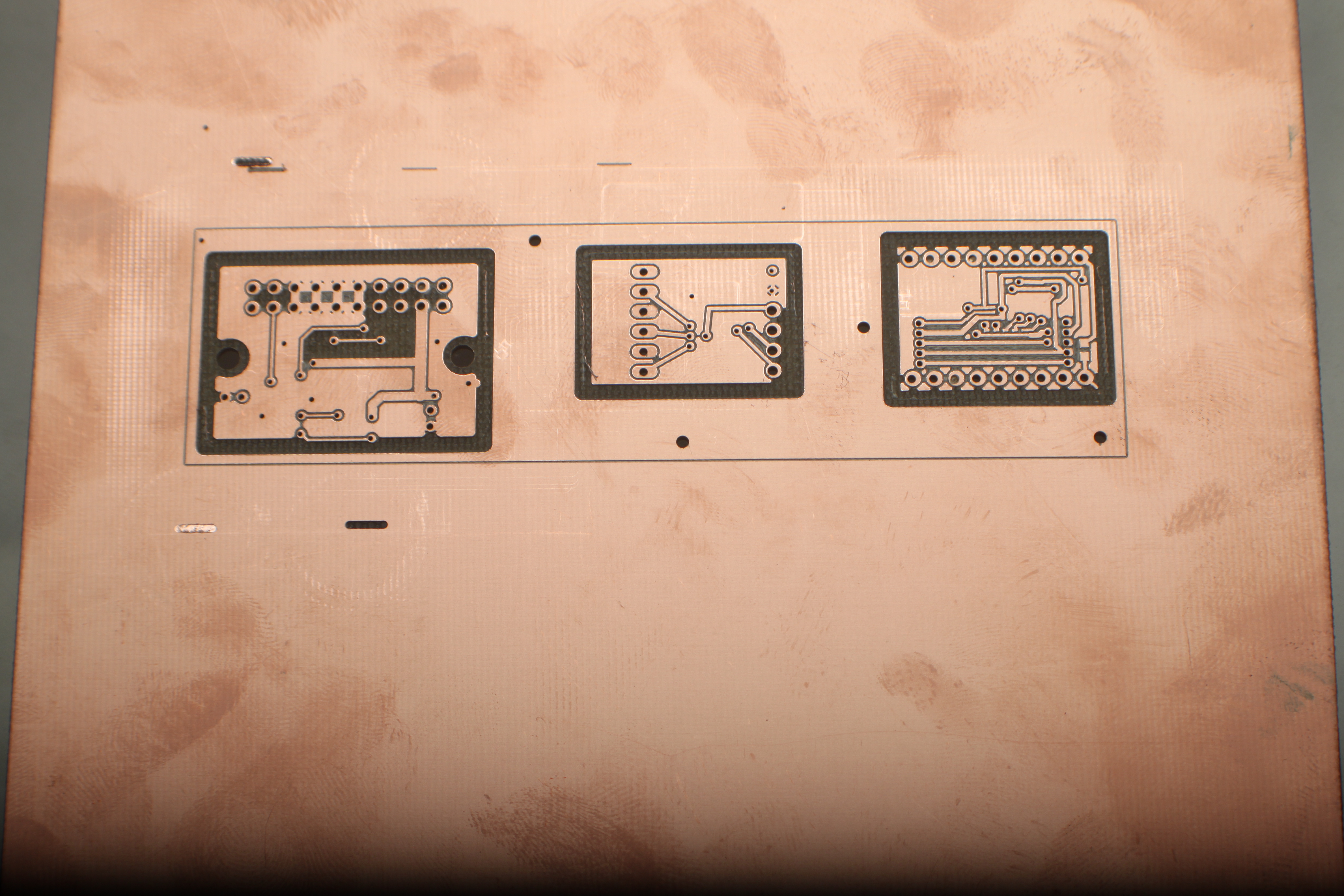
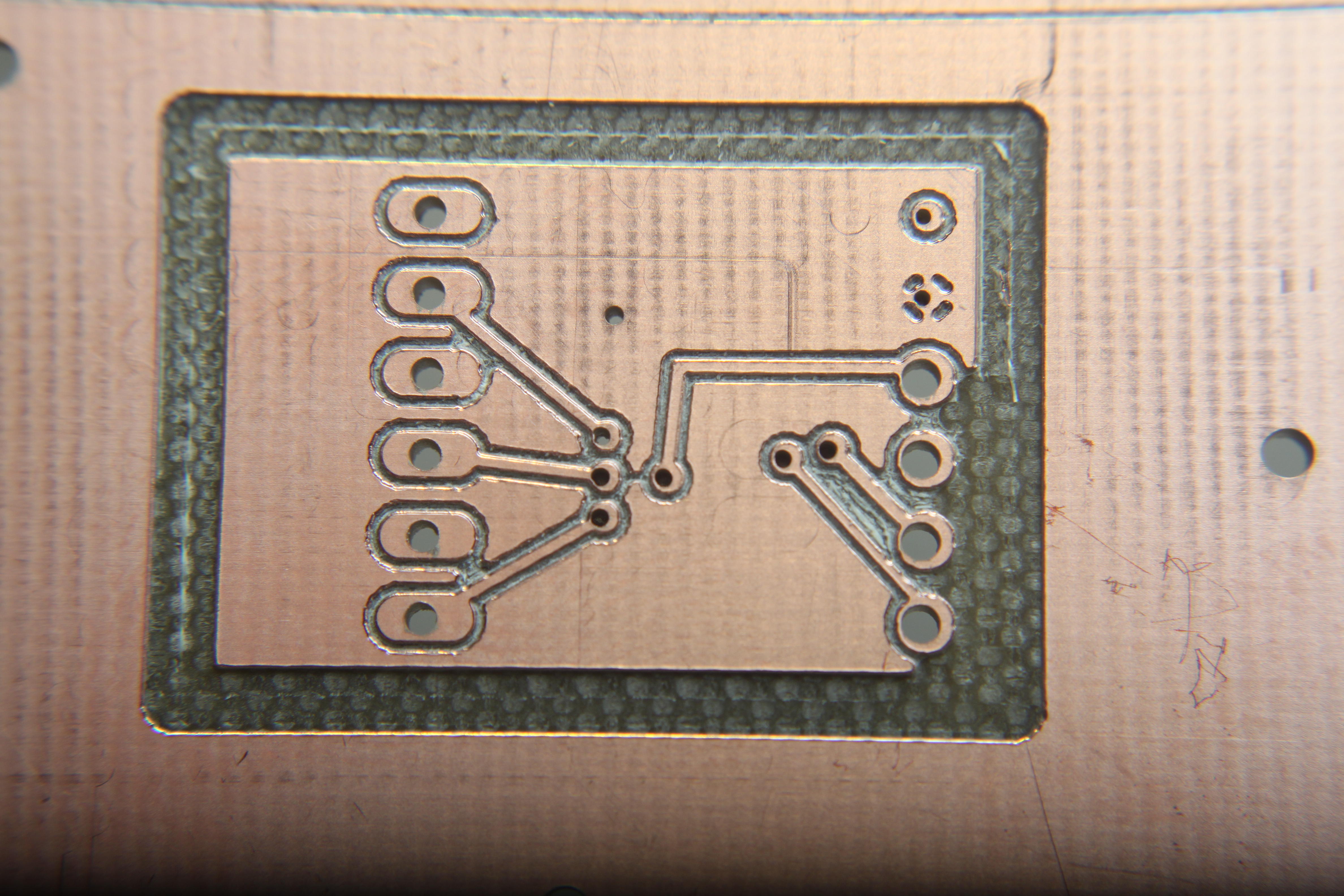
You are now done the 'Milling Bottom' step.
# Read Top
Turn off the vacuum system, flip the board over, and double check that it has the correct orientation. Turn the vacuum system back on to secure it in place.
Before you can start milling the features on the top side, you have to perform the 'Read Top' step, so the S62 can determine the board's relative position.
Select the 'Read Top' step from the task pulldown menu. Click 'All +', then click 'Start'. Proceed with the fiducial reading procedure, exactly as you did for the 'Read Bottom' step.
# Mill Top
The 'Milling Top' step is exactly the same as the 'Milling Bottom' step. Assuming the 'Read Top' step was successful, select the 'Milling Top' item from the task pulldown menu.
Click 'All +', then 'Start'. Follow the same steps as 'Milling Bottom'.
# Cutting Outside
Assuming both of the milling steps were successful (and the steps leading up to the milling steps, such as through-hole plating), you can now separate your circuits from the rest of the board.
This step is called the 'Cutting Outside' step.
Select the 'Cutting Outside' item from the task pulldown menu. Click 'All +', then click 'Start'.
The S62 only needs 1 tool for this step - the contour router. Depending on your settings in CircuitCAM, it will use the Contour Router 1.0mm or the Contour Router 2.0mm.
If the S62 doesn't have the Contour Router that it needs in order to complete the Cutting Outside step, you will have to add it using the Tool Positions menu, just like you did in the Marking Drills, Drill Plated, Milling Bottom, and other previous steps.
Once it is complete, you can park the spindle, shut down the vacuum system, and remove your board.
The individual boards will cling to the big board by some very thin struts left behind by the contour router. Simply clip these with sharp cutters, or carefully press on your boards until the 'pop' free from the sheet.
You may wish to sand or file the rough edges left by the contour router. Use caution not to cut yourself in this process.
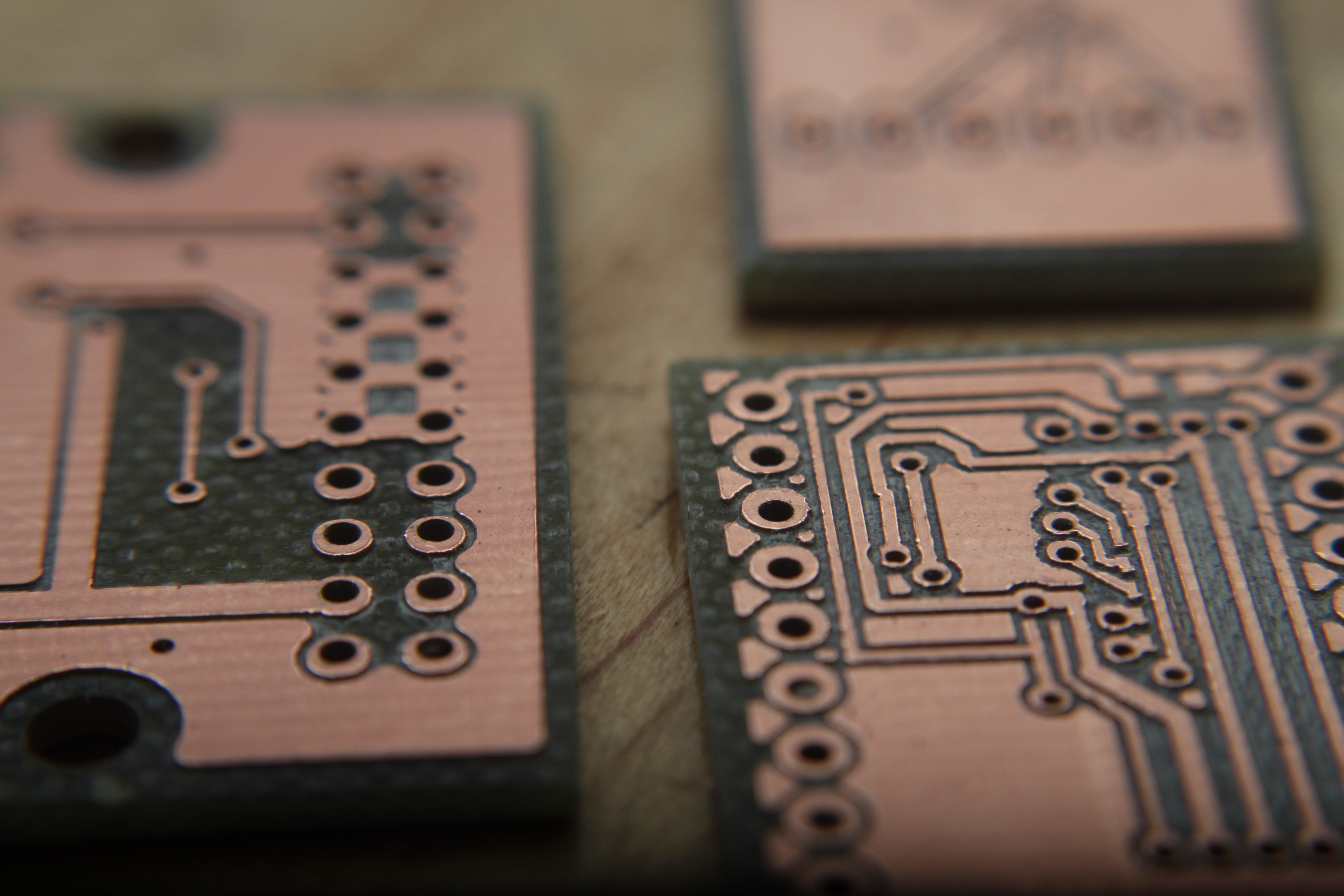
Below is an image showing an example of what your boards might look like after they have been separated from the sheet and the edges sanded. 
# Finishing
When you're done, exit the Board Master software. As the software is closing, it will want to drop the tool that it is holding. You will see a dialog box like the one below.
Click 'Yes'.
The software will also warn you that once you quit you cannot make any more boards, unless you restart the software, and import your LMD file from Cicuit CAM again.
If you're sure that you're finished, click 'Yes'. 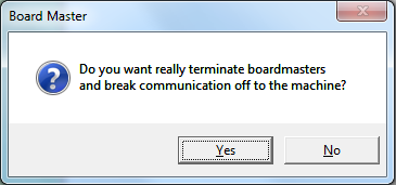
Next the software will want to move the spindle to the 'Home' position. This is not the same as the 'Park' position. Ensure that you have cleared off your board from the vacuum table, because you won't be able to access the vacuum table once the S62 has gone to its 'Home' position. 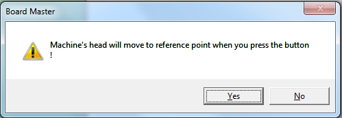
Finally, Board Master will ask you if you want to save the settings and other information from the current session. This can be valuable if you intend to return later and make more of the same circuit that you just completed.
If you want to save, click 'Yes', and save the job file to the same directory as your Eagle files, Gerber files, and LMD file.
If you're certain that you won't need to return to make more of the same circuit in the future, you can click 'No'. 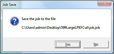 \\
\\