These are instructions for assembling the IR sensor and motor leads, you should do these in order!
The rest of the kit should be pretty simple to put together
TAKE ALL OF THE PAPER OFF THE PLASTIC PARTS BEFORE ASSEMBLY (UNLIKE PHOTOS)
Motor Leads
1) Attach the motor mounts to both the motors and use the screws and nuts in the bag to fasten to the chassis
2) Pull the motor cables up through the hole in the chassis and orient the plugs so the red line is on the right side for both motors
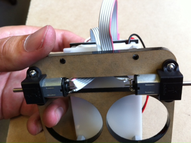
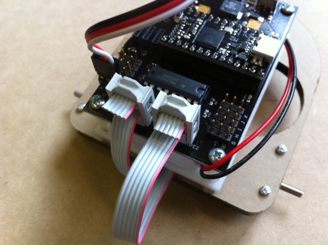
3) Plug the leads into the motor sockets on the MX board.
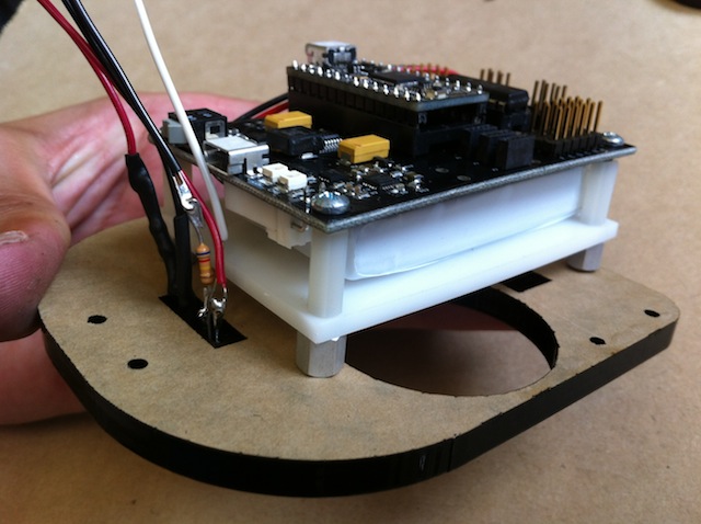
Sensor Mount
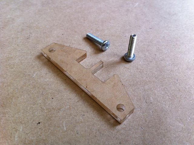
1) Find the sensor holder piece and the 2 1/2" 4-40 screws in your kit
2) Put the sensor through the front hole in the chassis and put the sensor mount through the hole with orientation as shown
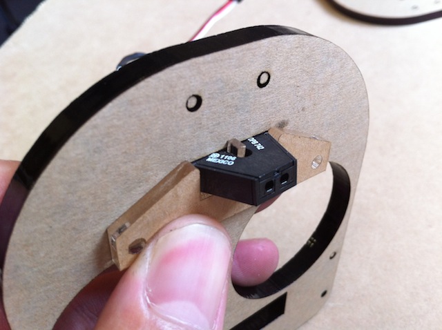
3) Secure the holder with the two 1/2" 4-40s into the MX board (make sure the MX is oriented as shown!)
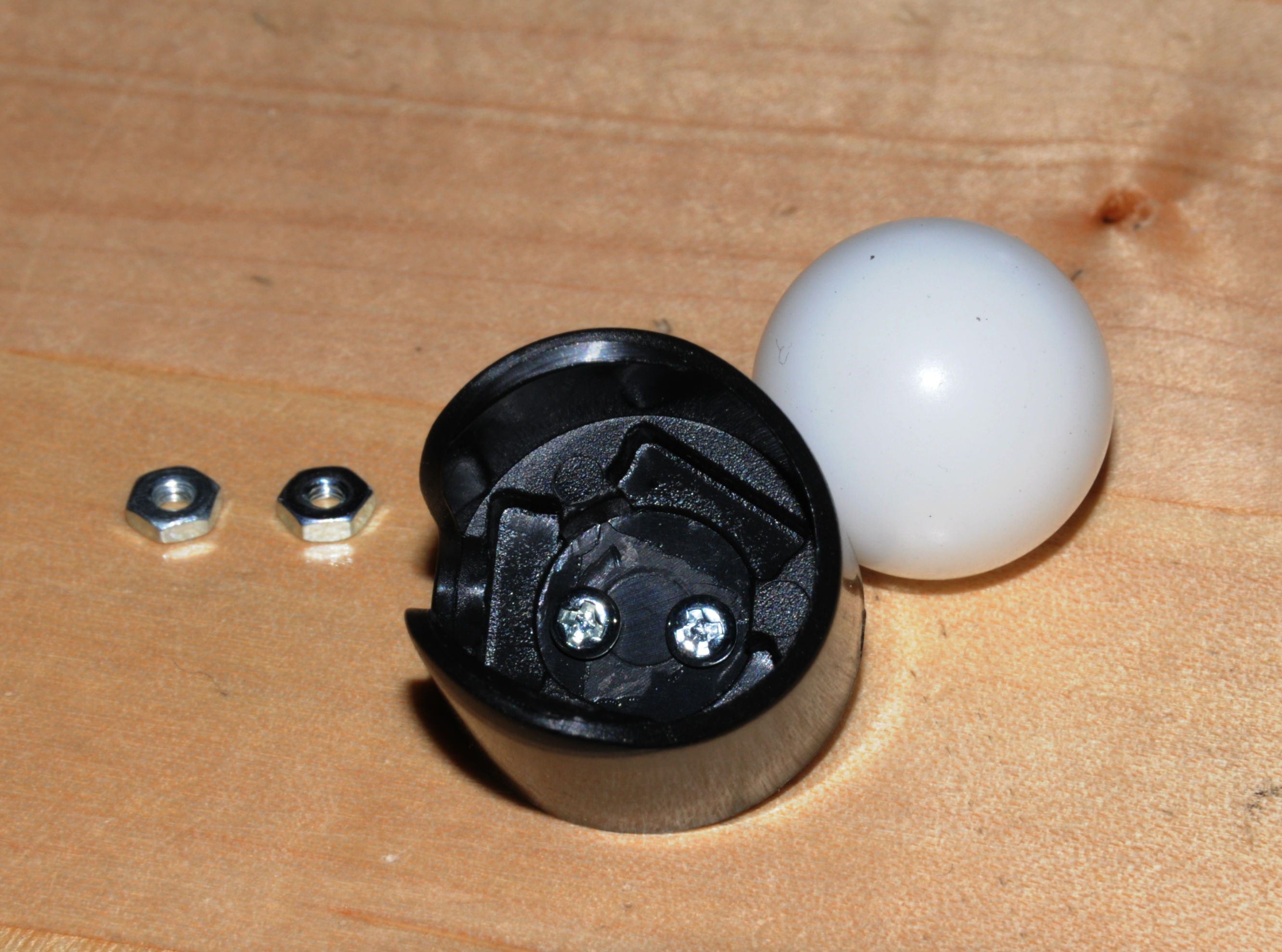
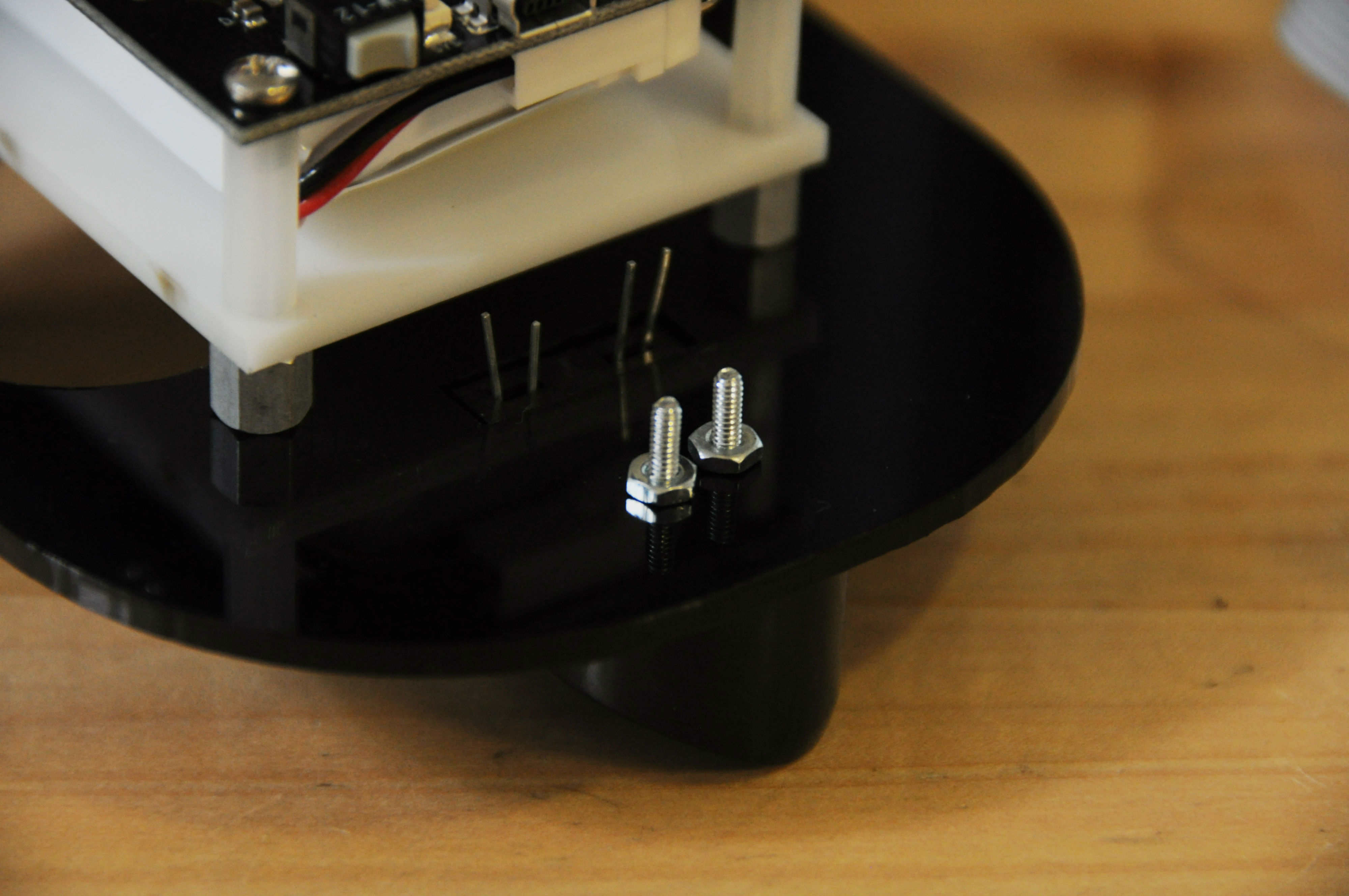
Front Castor
Use the longer 2-56 screws that are floating free in the baggie to secure the castor onto the chassis. The caster should come with two spacers, but you do not need to use them.
500px
500px
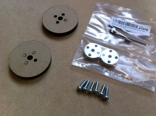
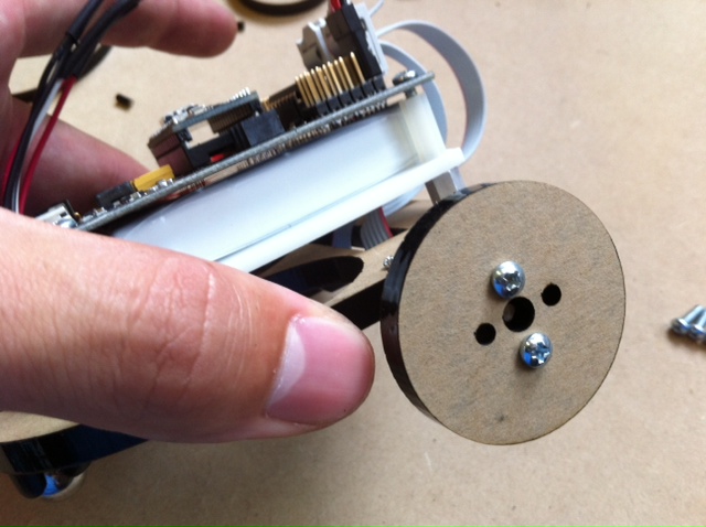
Use the remaining screws, should be (6) 3/8" 4-40s to fasten the back of the MX board and use two for attaching each wheel to a hub.
If you have questions ask the TAs, you shouldn't have to force any of the hardware into place!