MEAM.Design - MAEVARM - Sparkfun/Nordic RF Communications module
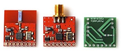
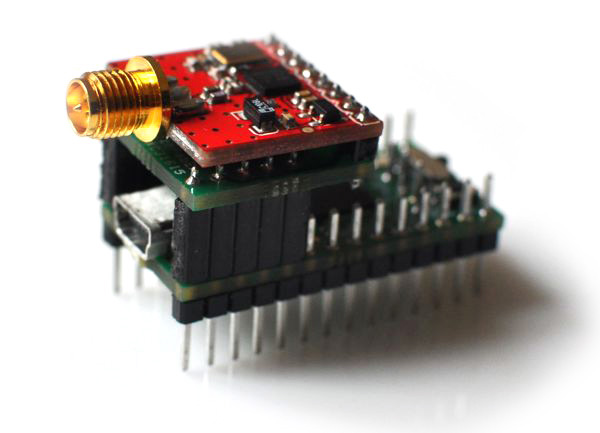
Shown above are two pre-built wireless modules from Sparkfun, along with a board that can be used to adapt the pinout directly to the M1/M2, as shown below:
Testing your hardware
Once you have everything soldered together (and at other times if you think you may have killed a wireless board), you can use the pre-compiled code available in the following zip file to test communication between two M1s/M2s.
Inside the zip file you will find two hex files, ping.hex and pong.hex. If you upload ping to one M1/M2 and pong to another (see here for how to do this using dfu-programmer on a mac), you should see them pass a packet back and forth, represented by the green onboard LED. If the one with the packet cannot transmit it back within 50 tries, the red onboard LED should illuminate. If such a failure occurs, they *should* be able to re-establish communications on their own, but you may need to reset one or the other to get it going again.
Getting started with your own code
First, download the header and code files from here, and place them in the same folder as your main.c file (this was last revised to version 1.4.0 on October 16, 2010):
If you're using AVR Studio, you will then need to right-click on the Source Files folder, and select Add Existing Source File(s)..., then select the maevarm-rf.c file. If you're using Windows OS with Option 2, place maevarm-rf.c in src/. If you're using Mac or Linux with Option 1, edit your Makefile to add "maevarm-rf.o" after "main.o" on the OBJECTS line. If you're using Mac or Linux with Option 2, place maevarm-rf.c in src/.
Now, as described in the header file, this will give you access to five public functions:
void RFsetup(char* recvAddr, char packet_length);
| Initialize the RF subsystem | ||
char RFRXdataReady();
| Check to see if new data is available. Returns a 1 if data has been received, 0 if the buffer is empty. | ||
void RFreceive(char* buffer);
| Read the most recent message from the n-element, 8-bit receive FIFO buffer and place the result in memory. Calling this function will read from the buffer until it's empty and return only the last message - the buffer is only 3 deep, and if it gets full new messages are ignored. Note - this function will place n bytes into memory, and if your array is not suitably sized you may be stomping on other data. | ||
void RFtransmit(char* txData, char* destAddr);
| Temporarily suspends receive mode and transmits a char array to a specific wireless node. This will only send one packet, and does not check for receipt. It will return the system to receive mode when finished. | ||
char RFtransmitUntil(char* txData, char* destAddr, char txTries);
| Temporarily suspends receive mode and transmits a char array to a specific wireless node up to a specified number of times. If no acknowledgement is returned from the other node, it will retransmit up to txTries times. The routine will return a 0 if unsuccessful, or the number of tries it took before success. It will return the system to receive mode when finished. | ||
For example, the following code will listen for messages, and if the first element of a received message happens to be 0xFF, it will transmit a message up to 50 times.
#include "maevarm-rf.h"
#define PACKET_LENGTH 4
char incoming[PACKET_LENGTH] = {0, 0, 0, 0}; // container for incoming messageschar outgoing[PACKET_LENGTH] = {0, 1, 2, 3}; // default outgoing messagechar me[5] = {0xAB, 0xAB, 0xAB, 0xAB, 0xAB};char you[5] = {0xCD, 0xCD, 0xCD, 0xCD, 0xCD};
int main(void){char success = 0;RFsetup(me,PACKET_LENGTH);while(1){if(RFRXdataReady()){RFreceive(incoming);if(incoming[0] == 0xFF){success = RFtransmitUntil(outgoing, you,50);}}}}
Using interrupts to handle incoming packets
If you would like to use interrupts to handle the reception of packets, utilize the fact that whenever a valid packet is received by the wireless chip, the line tied to pin B5 of the M1 will go low. You can sense this using pin-change interrupt PCINT5. To configure, use the following:
set(PCICR,PCIE0); // enable pin-change interruptsset(PCMSK0,PCINT5); // demask PCINT5sei(); // enable global interrupts
ISR(PCINT0_vect){if(!check(PINB,5)){ // change was high-to-low...}}